
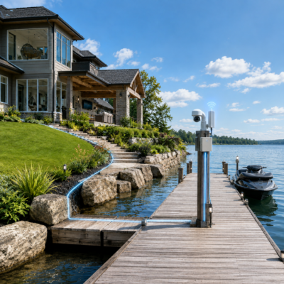
Remote connectivity succeeds when integrators stop thinking of fiber as an extended cable and start treating every gate, dock, garage and outbuilding installation as an integral network node.
Front gates, docks, detached garages and remote buildings are no longer peripheral spaces. They support security cameras, intercoms, access-control devices, wireless access points, automation systems, lighting controls, audio systems and other connected technologies.
The question is no longer whether the network needs to reach these locations — it is how to reach them without creating an unreliable, difficult-to-service extension of the main building.
Fiber optic cable is often the best backbone for the job. It supports long distances, provides substantial bandwidth and avoids many of the electrical issues associated with copper connections between buildings. However, installing fiber is only one part of the solution. A dependable remote connection also requires compatible electronics, appropriate power, environmental protection, testing and room for future expansion.
For integrators new to fiber, the most important principle is simple: Do not design a remote cable run. Design a remote network node.
>
Why Fiber Is Ideal for Remote Connectivity
Traditional twisted pair cable performance is generally limited to 100 meters or 328 feet. That distance includes patch cables, service loops and the actual trunk cable—not simply the straight-line distance between two buildings. Gates, docks and outbuildings can quickly exceed this limitation once the cable follows driveways, underground conduit, pole risers or other indirect routes.
Fiber eliminates this distance constraint for most residential and commercial applications while also offering several other advantages.
Fiber carries information as light rather than electrical current. An all-dielectric fiber connection does not create a conductive data path between structures, helping isolate different ground potentials and reducing exposure to electromagnetic and radio interference. This is especially valuable when connecting locations with separate electrical services or installing cables near motors, pumps, gate operators and other sources of electrical noise.
Plus, this all-dielectric construction also means fiber cabling is immune to static electricity, surges and lightning strikes — all common concerns when running cables outdoors.
Fiber’s capacity is equally important. A connection initially installed for one network device may eventually support multiple cameras, access points, controllers and audio-visual devices. When the pathway is difficult or expensive to install, choosing a backbone that can accommodate future applications protects both the integrator and the property owner.
>
Think of the Remote Location as a Micro-IDF
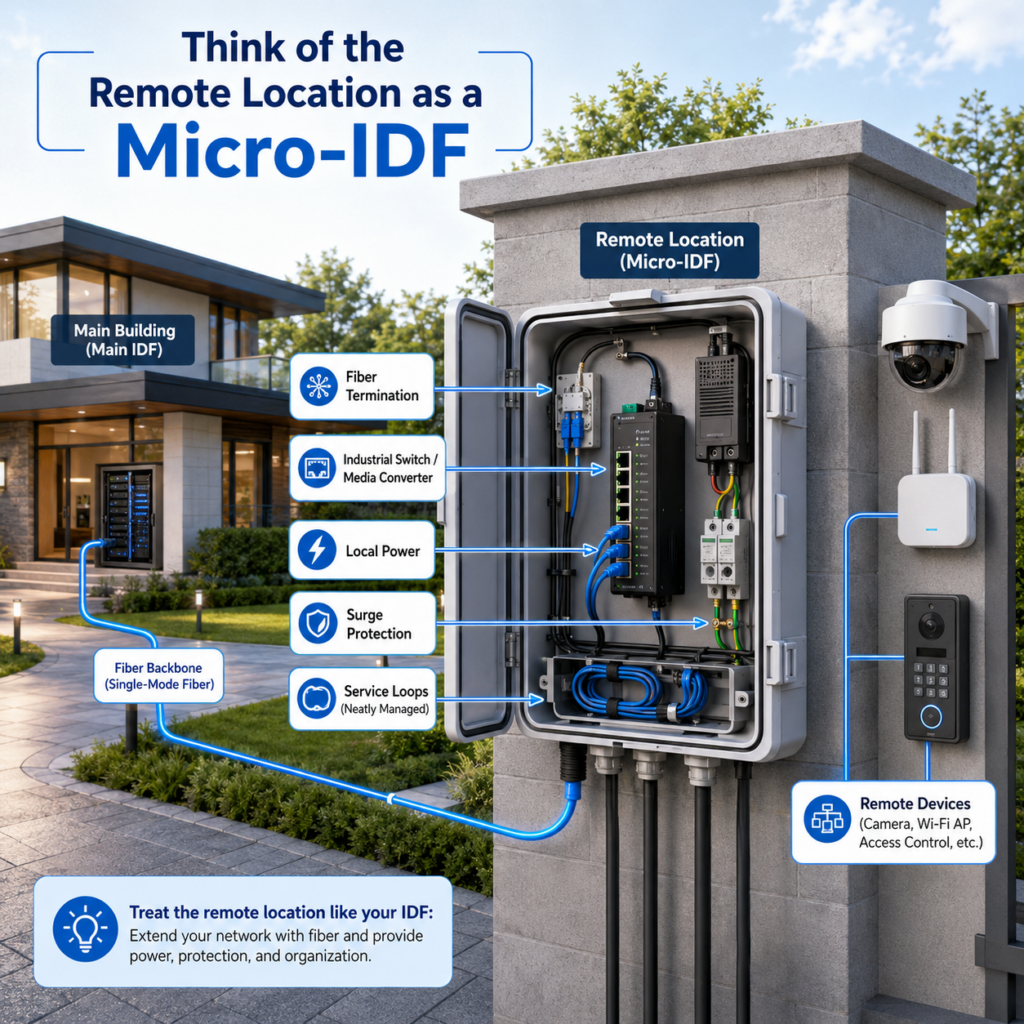 An intermediate distribution frame, or IDF, is a secondary network location that distributes connectivity to nearby devices. A gate pedestal, dock enclosure or detached garage may be much smaller than a traditional telecommunications room, but it should be designed around the same basic principles.
A properly designed remote node typically includes:
- A protected fiber termination point
- A media converter or fiber-enabled network switch
- Local power and, when required, PoE capacity
- An environmental enclosure
- Surge protection or backup power where appropriate
- Service loops, cable management and labeling
- A convenient location for testing and maintenance
This approach is more reliable than running fiber directly to a loosely mounted converter or leaving connectors and power supplies inside an undersized utility box. A proper enclosure protects the connections, maintains bend radius, organizes excess cable and creates a defined service point for future work.
>
Step 1: Design from the Devices Backward
Before selecting your fiber construction, document what the remote location must support.
Start with the devices. A front gate may need a camera, intercom, card reader and gate controller. A dock may require wireless access points, surveillance cameras and audio equipment. A detached garage may eventually need a complete local network supporting cameras, workstations, entertainment and automation.
For each device, identify:
- The required network connection
- Maximum bandwidth
- PoE type and maximum power consumption
- Environmental operating range
- Required uptime
- Whether remote management is needed
Do not size the system solely around the first device being installed. Include reasonable capacity for the next camera, access point or control system. Adding a larger switch or additional fiber strands during the initial installation is usually far easier than reopening a trench or replacing a filled conduit.
The good news is most fiber constructions support significantly more bandwidth than twisted pair — the limitation is typically the equipment plugged into the ends.
>
Step 2: Choose the Right System Architecture
The architecture depends primarily on the number and type of devices at the remote location.
For a single device, a media converter pair can be an efficient choice. Media converters simply connect to fiber optic cable runs and adapt optical fiber-ready signals to electrical twisted pair signals. Depending on model, some media converters even inject PoE into the copper connection.
When several devices share one location, a fiber-enabled PoE switch is generally the better design. This architecture consolidates the electronics, reduces the number of conversion devices and provides room for expansion. A managed switch can also support VLANs, port monitoring, traffic prioritization and remote troubleshooting.
Industrial switches are particularly important in unconditioned spaces. ROBOfiber industrial models available through Future Ready Solutions include fiber uplinks, multiple copper ports, PoE options and operating temperature ranges designed for harsh environments.
For applications with multiple remote locations, such as several gates, buildings or outdoor destinations, a star topology is usually the easiest to understand and service. Each location receives a dedicated fiber home run from the main building or a central distribution point.
Daisy-chaining remote switches may reduce cabling, but it also creates dependencies. A failed switch, damaged cable or power outage at one node can disconnect every device downstream. Daisy chains and ring topologies can be effective when deliberately engineered, but a straightforward star design is generally more appropriate for a novice fiber installer.
>
Step 3: Select the Fiber, Strand Count and Connectors
For many new remote-property installations, single mode (OS2) fiber is the most logical cable option. It provides substantial distance headroom and supports future network upgrades without replacing the installed cable. Multimode fiber remains appropriate when matching an existing multimode infrastructure or a specific electronics platform, but the fiber and transceivers at both ends must match. Note that the maximum distance for most multimode applications is around 300m or 1,000 feet.
Do not install only the minimum number of strands required to activate the link. Standard duplex Ethernet optics generally use one strand to transmit and another to receive. A two-strand cable may technically operate the system, but it provides no spare capacity.
For most remote links, consider installing at least four strands and often six or more. Spare strands support future services, provide a replacement if a termination is damaged or accommodate a second independent connection. The trunk cable is typically the most difficult component to replace, so use the initial installation to create capacity.
For most modern fiber optic devices, LC connectors or SC connectors are the default connection type. For connections before the modem, such as telecom and ISP feeds, SC/APC (angled) connectors are often used. For connections after the modem, such as with transceiver modules, switches and extenders, LC/UPC (flat) connectors are used. APC and UPC connectors use different end-face geometries and should not be intermixed on the same cable run.
When using transceivers (commonly known as SFP modules), other variables must also be specified for compatibility:
- Network speed, such as 1Gb or 10Gb
- Single mode or multimode fiber
- Operating wavelength
- Duplex or bidirectional operation
- Connector format
- Supported distance
- EEPROM programming and brand compatibility
A transceiver that physically fits an SFP slot is not automatically compatible with the switch or the transceiver at the opposite end, though the majority of products available from Future Ready Solutions leverage generic EEPROMs for the widest range of compatibility in the industry.
>
Step 4: Match the Cable Construction to the Pathway
“Outdoor fiber” is not one universal cable type. The correct construction depends on whether the cable is installed in conduit, directly buried, exposed above ground or transitioned into a building.
Installing in buried conduit. Underground conduit should be treated as a wet environment. Use an outdoor-rated or indoor/outdoor cable designed to tolerate moisture and temperature changes and, of course, survive the stress of the pull. Double jacket and ruggedized constructions are frequently used for these pathways.
Conduit also provides physical protection and makes future cable replacement easier. Include a spare pull string and consider installing additional conduit or innerduct when the pathway is difficult to access.
Directly burying underground. Cable placed directly in soil must be specifically rated for direct burial. Armored direct burial cable provides additional protection from crushing, abrasion and rodents. Do not assume that a heavy armored direct burial cable is also the best choice for a conduit pull. Its larger diameter, weight and limited flexibility may make it difficult to install through bends. Always follow the cable manufacturer’s pathway recommendations and consult your representatives at Future Ready Solutions.
Installing exposed above-ground runs. Cable exposed on a wall, pole, dock or other structure must have a UV-resistant and weather-resistant jacket. It must also be supported correctly and protected from impact, abrasion, animals and routine maintenance activity. Direct burial cable is often used in these applications due to its strength and ratings.
Installing at building entrances. Outdoor-only cable may need to transition to an indoor-listed cable near the building entrance. An indoor/outdoor-rated construction may allow a continuous run, but installers must verify the cable listing and applicable local code requirements.
Future Ready Solutions’ partner Cleerline offers double-jacket, ruggedized, armored direct-burial and other cable constructions designed around different outdoor pathways. Selecting the construction based on the environment—not simply the fiber type—is essential to long-term performance.
>
Step 5: Develop a Complete Power Strategy
Fiber carries optical data. As discussed above, it does not carry electrical signals and therefore it does not power the endpoint.
This distinction is one of the most common sources of confusion for installers transitioning from twisted pair. A copper PoE cable can deliver both data and power to a device. A fiber connection requires another power source at the remote location.
Common options include:
- Local AC power feeding an industrial PoE switch
- Local AC power feeding a media converter and PoE injector
- A properly engineered low-voltage power circuit
- A solar and battery system designed around the full equipment load
- A purpose-built hybrid fiber and power cable where permitted
Calculate the total PoE budget, not just the number of available ports. Use each device’s maximum rated power consumption, including camera heaters, infrared illumination and other high-load operating modes. Leave capacity for switch consumption, expansion and equipment startup.
Critical remote systems may also require backup power. A UPS at the main rack protects only the head-end equipment. If the remote switch loses local power, the fiber connection will remain dark regardless of the condition of the main network.
Surge protection should also be considered for remote AC circuits and for copper cables that leave the protected enclosure. Metallic armor and other conductive elements must be bonded or grounded according to the manufacturer’s instructions and applicable electrical requirements.
>
Step 6: Select Electronics and Enclosures for the Environment
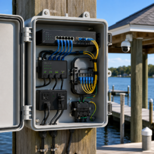 A consumer-grade network switch installed inside a sealed outdoor box is not an industrial system.
Remote electronics may experience high summer temperatures, freezing winter conditions, condensation, humidity, dust and salt laden air. Select switches, media converters and power supplies with operating specifications appropriate for the actual site.
The enclosure must also provide enough room for:
- Fiber bend radius and service loops
- Switches or media converters
- Power supplies and surge protection
- Cable glands and strain relief
- Heat dissipation or active cooling
- Safe access for testing
An enclosure’s NEMA or IP rating describes environmental protection, but it does not solve heat buildup or condensation. Vents, thermostatically controlled fans, heaters or other thermal-management methods may be required depending on the equipment and climate.
At docks, mount the enclosure above the expected splash and flood level, use corrosion-resistant hardware and create drip loops before cables enter the enclosure. At gates, protect the enclosure from vehicle impact, landscaping equipment and water from irrigation systems.
Future Ready Solutions offers Altelix weather-resistant enclosures designed to house networking equipment, power supplies, media converters and other electronics in remote applications. Enclosure are available with a variety of environmental features and can even be custom engineered depending on the need.
>
Step 7: Protect the Fiber During Installation
Fiber is durable when installed correctly, but excessive pulling force, tight bends, crushing and poor pathway preparation can damage the cable before the system is commissioned.
Before the pull, inspect the complete route for blocked conduit, sharp bends, debris, excessive conduit fill and locations where the cable could be pinched or abraded.
During installation pull from the cable’s designated strength members or, if pulling a factory pre-terminated cable, by properly installed pull mesh. Never pull directly on the glass fibers or connectors and stop immediately if the cable binds, excessively twists or kinks.
Always follow the cable manufacturer’s pulling-tension and bend-radius specifications. Leave a controlled service loop at each end. Do not cinch fiber tightly with standard cable ties or force excess cable into an undersized enclosure. Label every cable, strand, enclosure and switch port so another technician can understand the system without reverse-engineering it.
>
Step 8: Clean, Test and Document the Link
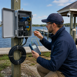 A fiber link should never be accepted simply because the switch displays a link light.
Connector contamination is a frequent cause of optical loss and, ultimately, intermittent system performance. Inspect and clean connector end faces before mating them, including factory-terminated patch cords. Dust caps protect connectors during storage, but they do not guarantee a clean end face.
Testing should progress through several levels:
- Visual inspection and cleaning: Verify the connectors are clean and undamaged.
- Visual fault locator testing: Confirm continuity, polarity and identify severe bends or breaks.
- Insertion-loss testing: Use a light source and optical power meter to measure the total loss of the completed link.
- OTDR testing: Use an optical time-domain reflectometer for longer, spliced or more complex links when event-level documentation is needed.
- Network commissioning: Verify negotiated link speed, device connectivity, PoE operation and remote management.
A visual fault locator (or VFL) is useful, but visible light at the opposite end does not gaurantee that the cable meets the optical-loss requirements of the integrated electronics. The Fiber Optic Association recommends testing continuity and polarity and measuring end-to-end insertion loss.
Record the fiber type, strand assignments, connector formats, transceiver part numbers, test results, enclosure locations and switch configuration. Photos of underground pathways, handholes and building entrances can also save substantial time during future service.
>
Leveraging Fiber in Common Remote Applications
Front gates. A front gate with a camera, intercom and access-control equipment will usually benefit from a small industrial PoE switch inside a protected enclosure. A typical design might include a six strand single mode fiber home run from the main network, a remote industrial switch with an SFP uplink and short copper connections to each gate device. Additional strands should be reserved for future devices or an independent control connection.
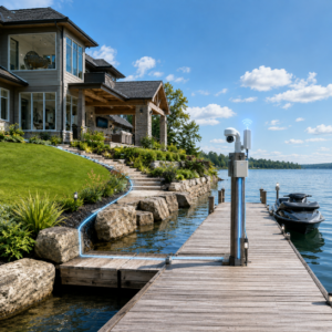 Piers and docks. A near-water installation must account for moisture, corrosion and condensation. Fiber can provide an electrically isolated data backbone from the main building, while a locally powered industrial PoE switch supports wireless access points and cameras. The enclosure should be mounted above likely water exposure, use sealed cable entries and provide enough thermal management for direct sunlight. Any local AC equipment and copper device cabling still require appropriate surge protection.
Detached garages and remote buildings. A garage or outbuilding should be treated as a small secondary network facility. Terminate the fiber in a wall-mounted enclosure or compact rack, then connect it to a managed switch supporting the local access point, cameras, AV equipment and automation devices. Where multiple users or high-bandwidth applications are expected, consider a higher-capacity uplink rather than designing only around the immediate devices. Add local backup power when security, communications or access systems must remain available during an outage.
Remote security and monitoring. Security cameras are among the most common reasons to extend connectivity beyond the main building. Cameras may be installed at entrance gates, along long driveways, near docks, around parking areas or on remote structures where standard copper Ethernet cannot reliably reach. A typical fiber-based camera system uses fiber to create the long-distance backbone, then converts the connection back to copper near the camera. When several cameras are located in the same remote area, an industrial PoE switch with a fiber uplink is generally the more scalable design.
Remote wireless access points. Outdoor living areas, docks, detached buildings, large properties and recreational spaces increasingly require dependable Wi-Fi coverage. Extending a wireless network to these locations is not simply a matter of installing a more powerful access point — the access point still needs a reliable wired connection back to the network. Fiber provides a high-bandwidth backbone that can reach the remote location without the distance restrictions of twisted pair Ethernet. At the remote end, a media converter, PoE media converter or fiber-enabled PoE switch converts the optical connection into the copper Ethernet and power connection required by the wireless access point.
Extended ISP demarcation locations. Incoming fiber-to-the-home internet service can also be extended or relocated using standard fiber optic cable, connectors and tools. It’s important to note connections before the modem require single mode cable and APC connectors (the green ones). Most services only need a single fiber strand (called simplex); however, it’s a common practice to pull two or more strands for expansion and redundancy. The overall cost is typically minimal.
>
Build the Entire Remote Connection
A successful remote fiber installation is not defined by whether light reaches the opposite end. It is defined by whether the complete system remains reliable through weather, power events, equipment changes and future expansion.
Future Ready Solutions can help integrators assemble the complete architecture, including Cleerline fiber cable and connectivity, ROBOfiber media converters and industrial switches, Altelix outdoor enclosures, Cleerline fiber termination and test equipment, and Xtreme Power protection solutions.
The larger lesson is that remote connectivity should not be approached as a one-off cable extension. Treat every front gate, dock, garage and outbuilding as a managed network node. When the fiber, electronics, power, enclosure and testing strategy are designed together, integrators can deliver a connection that is easier to commission, easier to service and ready for whatever the property needs next.