
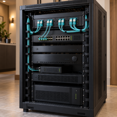
An equipment rack can look organized on installation day and still be difficult to service a year later. The difference often comes down to decisions made before the first component was mounted: where permanent cables terminate, how fiber enters the rack and what a technician must move to replace a piece of equipment.
A fiber-first equipment rack gives those decisions priority. It plans fiber as the backbone for network and AV links where bandwidth, distance and expansion requirements favor an optical connection. Copper, HDMI and power connections complete the system around it. The design gives permanent cabling a protected home and makes routine changes accessible.
For integrators, this is an opportunity to deliver value that extends beyond the equipment list. Lowell provides the physical platform, Cleerline supplies the optical infrastructure and complementary Future Ready Solutions products help complete the rack. The objective is a system that will accommodate service and growth for year’s to come.
>
Start with the Connections the Rack Must Support
Begin by mapping the links between the main rack, secondary distribution points, displays and remote network locations. Identify what each connection must carry, how far it travels and which equipment will sit at each end.
Select the fiber type and optical hardware together. Single-mode and multimode fiber support different link designs, and the correct choice depends on the application, distance and equipment. Record the required speed, connector format, strand count and optical loss budget, which accounts for signal loss through the cable, connectors and splices.
For Ethernet links, also confirm that the optical modules are supported by the switches or converters and compatible with the devices at the other end. For audio-visual systems, follow the distribution platform’s network and transport requirements.
Finally, consider likely additions. A future outbuilding, another display zone or a second equipment rack may justify spare fibers, unused adapter positions and additional pathway capacity.
A useful question is: What would have to change if the customer added the next connection? Determining an answer early helps determine where extra capacity is worth providing.
>
Choose the Rack for Usable Space and Service Access
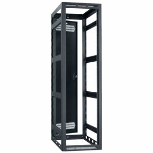 Rack height is only one part of the selection process. Usable depth must accommodate the equipment chassis, connector bodies, cable bends and access needed to install or remove connections.
The Lowell LGR AV Rack Series provides adjustable mounting rails and multiple cable lacing points, holes and knockout panels. These features give the designer a wide variety of options for positioning equipment and establishing cable pathways.
For smaller installations where rear access is difficult, the Lowell LWR Swing Open AV Rack Series provides a front equipment section that swings away from its backbox. That makes connections accessible in a wall installation, provided the design includes clearance for the rack to open.
Relocatable racks introduce another design requirement: the cabling must accommodate the full movement. Plan supported service loops that allow the rack to open without pulling on connectors or trapping fiber at the hinge.
Before selecting the rack, account for equipment weight, mounting support, room access and planned expansion. A spare rack unit is useful only if the cable pathways, power capacity and working clearances can support the equipment that eventually occupies it.
>
Give Permanent Fiber a Protected Termination Point
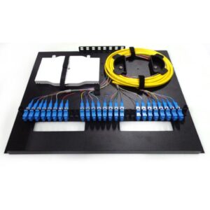 A dedicated fiber enclosure creates an organized transition between the installed backbone and the patch cords connected to active equipment.
Cleerline rack mount fiber distribution enclosures offer this approach in 1RU, 2RU and 4RU configurations. They accept compatible LGX adapter plates or modules and provide slide-out access for termination and fiber management. The 1RU model accepts three adapter plates, allowing a compact rack to establish a defined fiber distribution point.
Include the required adapter plates, termination or splice components and patch cords in the design. An empty enclosure provides the framework and its internal configuration determines what it can connect.
Place the enclosure where incoming fiber can reach it through a supported route and where a technician can open the tray, inspect connectors and trace labels. Positioning it near the equipment it serves can also simplify patching.
Future Ready Solutions offers custom-terminated Cleerline SSF fiber with selected cable lengths, connector types and optional pulling protection. This can help when the route and termination locations are known in advance. Measure the actual pathway and include planned service slack before ordering.
This arrangement creates a clear maintenance boundary. When equipment changes, the technician can work at the patching interface while leaving the installed backbone secured.
>
Manage Fiber for Handling and Future Changes
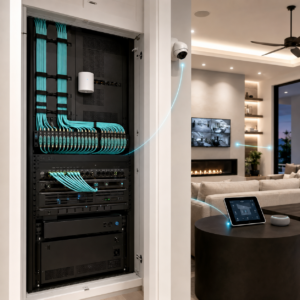 Fiber routing deserves attention at every transition: the cable entry, enclosure opening, patch panel and equipment port.
Cleerline’s SSF™ fiber uses a protective polymer construction designed to improve optical strand strength and flexibility. That added durability is valuable during installation and handling. Select the complete cable construction for its intended environment and follow its installation requirements.
Always follow Cleerline’s minimum bend radius, pulling tension and crush limits for the selected cable. Those limits can differ between cable constructions and between installation and long-term use. Provide supported service loops and protect cables where they cross edges or enter enclosures.
Within the rack, use appropriate cable managers and lightly secured reusable straps. Keep fiber out of tightly compressed bundles and leave connector releases accessible. Support incoming cable to keep its weight off the terminations.
Give power cords and signal cabling clearly organized routes. For fiber, this helps prevent mechanical interference and makes circuits easier to trace during service.
Check the routing with doors closed and every movable tray or rack section in its operating and service positions. A cable path that looks acceptable while the rack is open may become pinched or strained when it is closed.
>
Keep Local Patching Compact and Mount Conversion Equipment Properly
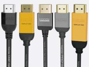 Short copper and HDMI connections remain useful within a fiber-first rack. Select their lengths around the actual route and the movement required for service.
Kordz PRO SlimCat Cat6 patch cords use a 3.9mm cable diameter and compact connectors, providing an option for reducing bulk around network patching. Select the appropriate cable category and verify the complete channel’s requirements for speed and Power over Ethernet (PoE).
For local AV connections, Kordz HDMI cables combine compact connector assemblies with 48Gbps capability and closely spaced length options. Their rack-oriented design helps installers match the cable to the route without accumulating unnecessary slack.
Plan optical conversion with the same care. Where a switch has a suitable supported fiber uplink, the connection can terminate directly at that interface. Where conversion is needed, give the converter a secure mounting location, accessible connections and a defined power source.
For example, the ROBOfiber LFC-10GT-SFP converts between 10G copper Ethernet and an SFP+ optical interface. Compatible units can be installed in the LFC-CH12 chassis, which accommodates up to 12 converters in 1RU. The optical modules are selected separately.
The design benefit is orderly aggregation: conversion equipment becomes an accessible part of the rack, with its mounting and power requirements included from the beginning.
>
Design Power and Cooling Around the Complete System
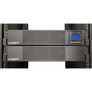 A passive fiber infrastructure still depends on powered electronics to deliver a working system. Switches, optical transceivers, AV processors and media converters all belong in the power and thermal plan.
Size the UPS using the connected load, both watt and volt-ampere (VA) limits, desired runtime and expected growth. Include the power a PoE switch must supply to its connected devices. Check the selected UPS model’s runtime data at the intended load.
The Xtreme Power P91 Li UPS Series provides online double-conversion protection using lithium iron phosphate batteries. It is one option for supplying conditioned power and battery backup to the rack’s essential electronics.
For distribution and service, the Xtreme Power SPDU Series offers individual outlet metering and remote outlet control. Those capabilities can help an integrator identify power consumption and restart selected equipment remotely when the management connection is available.
Consider the far end of each fiber link, too. A remote switch or converter needs its own power source. If the application must remain available during an outage, backup power at the main rack and the remote location must be planned together.
Cooling requires an equally deliberate approach. Follow each device’s airflow direction and clearance requirements, keep cable bundles clear of vents and provide a route for heat to leave the surrounding cabinet or room. Lowell fan panels with thermostat probes can add temperature-controlled ventilation where appropriate.
Validate temperatures with the complete system operating under a representative load and with doors and panels in their normal positions.
>
Commission the Rack as a Complete System
Plan acceptance testing before installation so the team knows what a completed rack must demonstrate.
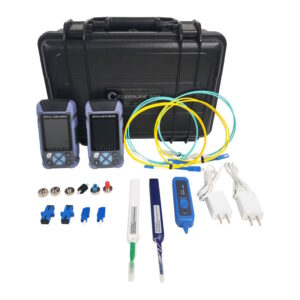 Inspect fiber connector end faces, clean as needed and reinspect before mating. Verify continuity and polarity so transmit and receive paths reach their intended ports, then measure insertion loss using the appropriate reference method and wavelengths. Compare the results with the project’s acceptance criteria and preserve the records.
Cleerline offers a fiber inspection video microscope, a connector cleaning kit and the SSF-TKITP-500 testing kit to support those tasks. The testing kit includes an optical power meter and light source for multimode and single-mode fiber, with stored results that can be exported through its PC software.
Label both ends of every link and identify panel positions, destinations, active fibers and spares. Record the optical module models and the power outlets serving important devices.
Finally, verify operation with the intended network traffic or AV signals. Check that doors close, trays move and planned service tasks can be performed without straining cables or disturbing adjacent connections.
The handover should give the next technician enough information to understand and maintain the system.
>
Build the Rack Around Its Next Service Visit
The value of a fiber-first rack becomes clear when the system needs to change. A switch replacement, a new display or an additional remote connection should have an identifiable place in the design.
Lowell racks and accessories provide the structure for access and organization. Cleerline fiber, enclosures and installation tools establish the optical infrastructure. Kordz patching, ROBOfiber conversion and Xtreme Power protection complete the connections around it.
For integrators, the commercial opportunity is to make future work more predictable. Protected permanent cabling, accessible patching and documented test results can help reduce the amount of troubleshooting and rework required when the system evolves.
Contact Future Ready Solutions for help designing your next fiber-first equipment rack and selecting the rack, fiber infrastructure, connectivity and power products for your application.