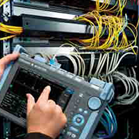
Fiber optic testers perform several distinct categories of tests, depending on whether you’re verifying basic continuity, measuring performance or certifying an installation to standards (TIA/ISO). Not all testers are built the same, and not all testers perform the same tests. Some are designed for the initial installation of optical systems, and some assist in the troubleshooting of previously installed systems.
Whether you’re working with fiber in a commercial building, a data center or a residential AV system, proper fiber testing ensures performance, reliability and long-term stability. But what exactly do fiber optic testers test?
This article explores the essential tests that various testers perform. For those new to the category, we recommend starting with a previous article — Fiber Optic Testers: Choosing the Right Tool — which provides a basic overview of popular fiber testing solutions available from Future Ready Solutions.
A wide variety of fiber-focused articles is available in the Future Ready Solutions News & Insights library.
>
Continuity and Polarity Tests
 One of the most basic (and essential) tests for fiber optic cable runs is continuity and polarity. Continuity confirms that light travels end-to-end through the fiber optic strand, whereas polarity verifies that the transmit (TX) side of one device is correctly connected to the receive (RX) side of the opposite device.
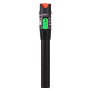
Ultimately, these tests are typically visual in nature and leverage a simple visual fault locator (VFL). The VFL is connected to one end of the cable and, assuming there are no breaks, cracks or severe bends in the fiber and light can travel from one end to the other, the opposite side is illuminated. If light is present, there is continuity in the cable. If light isn’t present, there is likely a break somewhere inline and a bright, visible light along the cable run will pin-point the issue.
Additionally, if there is continuity it’s important to confirm that polarity is also present. Fiber-based systems rely on TX ports connecting to RX ports and incorrect polarity, especially in duplex and MPO/MTP links, leads to signal failure.
>
Optical Power and Loss Testing (OLTS)
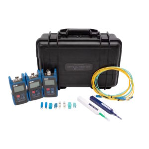 Optical power and loss testing (also known as Tier 1 testing) is the process of measuring the light intensity and total insertion loss using an Optical Light Source (OLS) and an Optical Power Meter (OPM). It ensures that a fiber optic run meets performance standards by measuring light output against a reference, which detects signal degradation from attenuation, connectors, splices or damage.
Optical power and loss testing is important because even if a link passes continuity, excessive loss can cause intermittent failures, reduced bandwidth or future service calls.
To test for optical power and loss, a stable light source or generator (OLS) and an optical power meter (OPM) are required. The OLS is placed at one end of the cable run and a reference power level is set (typically to 0 dB) to account for inline test jumper losses. The OPM is then placed at the other end and the meter displays the total loss in decibels, allowing for a pass/fail determination based on pre-defined budgets. It’s important to note the OLS and OPM must be set to the same wavelengths (850nm, 1310nm, etc.) according to the cable being tested.
Optical power and loss testing is essential for link certification, acceptance testing, warranty documentation and simply to verify if a cable run is performing to spec (i.e., troubleshooting). Different testers provide different features, and advanced kits will even save and print test results allowing for the formal certification of cable runs.
>
Optical Time Domain Reflectometer (OTDR) Length to Fault Testing
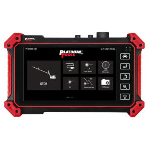 Optical time domain reflectometer (OTDR) testing is like a “radar” for cables, sending out light signals and measuring the time and intensity of reflections (backscatter) to map the cable. By doing so, OTDR testing maps the entire fiber route, identifying the exact location and severity of faults such as breaks, bends or poor splices.
In essence, OTDR testing doesn’t just tell you that a problem exists—it tells you where it is. This makes OTDR testing invaluable for troubleshooting long fiber runs and hidden issues behind walls, ceilings or underground pathways.
OTDR testing is essential for testing and troubleshooting backbones and trunk cables, cables that are permanently installed and not visible, outside plant (OSP) installations and advanced mission-critical applications where level of service is important.
>
Connector End-Face Inspection
 Dirty connectors are the number one cause of fiber failures. Even microscopic contamination can introduce enough loss or reflectance to cause signal instability—especially in high-speed networks.
Unfortunately, optical lenses are extremely small and it’s difficult to see debris or damage on a connector end-face, inside bulkhead connections or inside electronics’ ports.
Analog and digital microscopes are commonly used to inspect connections for contamination such as dirt, dust, oil and residue, or damage such as scratches, cracks and chips.
For best installation results, inspection should happen before any power, loss or OTDR testing to rule out local issues and save time troubleshooting.
>
A Final Note
For most commercial, residential, security and audio-visual installations, a best-practice testing sequence looks like this:
- Inspect and clean all connectors
- Verify polarity and continuity
- Perform power and loss certification
- Use OTDR testing when distance, complexity or troubleshooting requires it
Following this process reduces callbacks, prevents premature failures and ensures the fiber network performs as designed from day one.
Future Ready Solutions offers a wide variety of fiber optic testing solutions. Additional information is available online at FutureReadySolutions.com.